
Basic Countermeasures Equipment
2045B - FEEDBACK DETECTOR
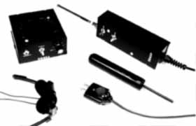
This unit covers the radio spectrum from 100 KHz to over 1000 MHz and detects many battery or AC and telephone line powered radio frequency (RF) and infrared (IR) optical transmitters by using the "feedback" technique. That's where the suspect transmitter hears the noise from the loudspeaker of the 2045B and the 2045B, in turn, detects what the transmitter hears, thereby causing a feedback squeal. Despite its simplicity, this detector offers a high degree of effectiveness and reliability. The system is supplied with the amplifier/speaker, probe assembly, RF antenna, AC input cable, optical (IR) probe, headset, instructions and carrying case. The amplifier is powered by 6 "AA" batteries while the optical probe contains a single "AA" battery (Alkaline always preferred).
The 2045B detects and locates radio frequency (RF) transmitters and carrier-current devices operating from 10 KHz to well over 1,000 MHz (1 GHz) as well as a variety of infrared (IR) optical devices by using the "feedback" technique. The unit demodulates the amplitude modulated (AM) component which occurs on most, but not all, RF sources. RF and carrier-current energy detected by the 2045P probe is fed through the shielded cable to the 2045A audio amplifier/ filter. Audio from the speaker is, in turn, heard by the transmitter thereby establishing feedback. The amplifier also contains a "clock" circuit that periodically gives the speaker a "kick" which, under some conditions, aids in establishing feedback.
TO OPERATE: Remove the 2045P (probe) and 2045A (amplifier) from the carrying case. Insert the shielded cable from the probe into the jack at the base of the amplifier. Place the LINE/ANT switch in the ANT (antenna) position and the band selector on HI. Mount the antenna on the quarter turn BNC connector on the probe and extend two or three of the heaviest or larger diameter antenna sections. The remaining smaller, movable sections should be fully collapsed. Place the switch on the amplifier (2045A) in the CLOCK position. Rotate the GAIN control to the point where the output hiss is at the loudest and most comfortable level. Hold the probe in one hand and the amplifier in the other. With the speaker facing towards the search area, i.e. wall, desk, chair, etc., begin sweeping a four foot wide area. Sweep first with the antenna held vertical; then horizontal; then perpendicular. Sweep the same area with the band switch in the MID and then the LO positions. If feedback develops, a transmitter has been located. Hold the antenna near where the feedback was established and reduce the GAIN until the feedback stops. Turn off the CLOCK. Move the antenna and speaker about until feedback is reestablished. By reducing the GAIN and moving the antenna and speaker in the direction that provides the greatest feedback the microphone in the transmitter will be located. Bear in mind that the microphone may be external from the transmitter.
To search for a wall socket transmitter or carrier-current device, place the input selector switch in the LINE position. Collapse and remove the antenna from the BNC connector. Insert the AC line probe into the jack adjacent to BNC connector (NOT the similar connector on the base of the amplifier!). This probe is protected to 500 volts DC or 50/60 Hz AC. Advance the GAIN to a comfortable level. Plug the AC line probe into a wall socket and, with the band selector in the HI position, move the speaker near and then around the socket. Check in the MID and LO band. RF transmitters within the socket most likely will be found on the MED and HI positions while carrier current devices most likely will be found on the LO and MID positions. If feedback develops proceed as above.
Test each and every AC outlet in the search area. Remember, there are usually two sockets in each outlet. .test both. Telephone lines can also be tested for carrier-current devices by connecting the AC line plug to the telephone line via a suitable adaptor or clip leads.
To detect IR devices, insert the plug on the optical probe (black tubular) into the jack on the base of the 2045A amplifier NOT the similar jack on the 2045P probe. At a distance of three feet the probe "sees" an area roughly two feet in diameter. Any fluorescent lamps in the search area should be turned off by removing the bulbs. Point the probe in the desired direction and slowly sweep the area. If feedback develops proceed as above. The IR probe contains a 1 1/2 volt "AA" battery which should last several years. The probe draws no power when in the dark, therefore, when the IR probe is not in use it should be kept in the closed carrying case.
The 2045B can be used with a headset (supplied). When using the headset the system will readily detect amplitude modulated transmitters, however, it will also detect many types of frequency modulated transmitters due to the fact that there is usually residual amplitude modulation on the carrier. The unit will not demodulate a well designed narrow-band frequency modulated (NBFM) transmitter. The only effect these transmitters have on the 2045B is to lessen the noise level heard through the speaker (quieting). Keep the GAIN at a comfortable level.
ALWAYS TURN THE UNIT OFF WHEN NOT IN USE.
The 2045A contains six "AA" batteries (Alkaline always preferred). To replace, remove the two silver screws on the sides of the amplifier. Carefully remove the cover, remove old batteries, insert fresh batteries making sure they are properly seated in the holder and replace cover and screws. Don't over-tighten. The single "AA" battery (again, Alkaline preferred) in the IR probe is changed by removing the two screws and carefully slipping out the battery holder.
The 2045P has a spare detector diode taped inside should the unit fail to detect properly.
As with any piece of electronic equipment, remove the batteries during periods of prolonged storage.
|
To be contacted for a confidential consultation please E-mail: jmatk@tscm.com
or send a letter via US Mail to:
or call:
URL: http://www.tscm.com/ |